![]()
Latest Jun 28, 2026 Real 3V0-25.25 Exam Dumps Questions Valid 3V0-25.25 Dumps PDF
VMware 3V0-25.25 Exam Dumps - PDF Questions and Testing Engine
NEW QUESTION # 12
An administrator is troubleshooting intermittent connectivity failures between two workloads connected to NSX VLAN segments using Traceflow. In-band Network Telemetry (INT) has been enabled in the NSX Global Configuration. How does Traceflow identify issues in a VLAN network?
- A. Traceflow cannot be enabled to analyze VLAN network segments in NSX.
- B. Injects ICMP traffic into the data plane and observes the results in the control plane.
- C. Injects synthetic traffic into the data plane and observes the results in the control plane.
- D. Compares intended network state in the control plane with Tunnel End Point (TEP) keepalives in the data plane.
Answer: C
Explanation:
Comprehensive and Detailed 250 to 350 words of Explanation From VMware Cloud Foundation (VCF) documents:
InVMware Cloud Foundation (VCF)and NSX,Traceflowis a powerful diagnostic tool designed to provide visibility into the logical and physical path of a packet as it traverses the SDDC. Unlike standard ping or traceroute utilities that use real ICMP traffic from the Guest OS, Traceflow operates byinjecting synthetic trafficdirectly into the data plane at the source point (usually the vNIC of a Virtual Machine).
When Traceflow is initiated, the NSX Manager creates a "trace packet" that mimics the characteristics of the traffic being investigated (such as TCP, UDP, or ICMP with specific headers). This synthetic packet is marked with a special metadata tag. As the packet moves through the virtual switches (VDS), logical routers (DR/SR), and distributed firewalls (DFW) on the ESXi Transport Nodes, each component recognizes the tag and reports an "observation" back to theCentral Control Plane (CCP). The CCP then aggregates these observations and presents them in the NSX Manager UI.
ForVLAN-backed segments, Traceflow functions similarly to how it works on Overlay segments. It tracks the packet as it is switched at Layer 2 and processed by any applicable distributed services. The inclusion of In-band Network Telemetry (INT)in modern VCF versions (5.x and 9.0) enhances this by allowing the synthetic packet to collect telemetry data from INT-capable physical switches in the fabric. This provides a
"hop-by-hop" view that includes both the virtual and physical segments of the journey.
Option A is incorrect because Traceflow is not limited to ICMP; it can simulate various protocols. Option C is incorrect as Traceflow fully supports VLAN segments. Option D is incorrect as it describes a state- comparison mechanism rather than the active injection process that defines Traceflow. Therefore, the injection of synthetic traffic to observe data plane behavior via the control plane is the verified mechanism.
NEW QUESTION # 13
An administrator has deployed a workload domain in VMware Cloud Foundation (VCF). The workload domain was deployed with NSX managers using the XL form factor. After deployment, the administrator realizes the NSX manager is oversized and needs to change to a smaller form factor. What should the administrator do to accomplish this task?
- A. Each NSX Manager must be redeployed.
- B. Each NSX manager must be resized using the API.
- C. Each NSX manager must be rightsized using VCF Operations.
- D. Each NSX manager must be resized through vCenter.
Answer: A
Explanation:
Comprehensive and Detailed 250 to 350 words of Explanation From VMware Cloud Foundation (VCF) documents:
InVMware Cloud Foundation (VCF), the lifecycle of the NSX Manager cluster is strictly managed by SDDC Manager. During the initial deployment of a Management Domain or the creation of a new Workload Domain (if using a separate NSX instance), the administrator selects a "Form Factor" (Small, Medium, Large, or Extra Large) based on the expected scale of the environment.
As of current VCF versions (including 5.x), theForm Factoris a parameter defined during the deployment workflow that determines the resource reservations (CPU/RAM) and the disk partitioning of the appliance OVA. Unlike a standard virtual machine where you might simply adjust the vCPU and RAM settings in vCenter, the NSX Manager appliance is an opinionated system. Changing resources manually through vCenter (Option C) is not supported and can lead to stability issues or "Out of Sync" errors within SDDC Manager, as the database and internal services are tuned for the specific size selected at install.
There is currently no supported "in-place" upgrade or downgrade for the form factor of an existing NSX Manager node via the UI or API (Option B). To change the size, the administrator mustredeploythe manager nodes. In a VCF context, this often involves using SDDC Manager to delete the cluster or manually replacing nodes one by one-essentially deploying a new node of the correct size, joining it to the management cluster, syncing the data, and then removing the old, oversized node.
VCF Operations(formerly vRealize Operations) can provide "Right-sizing"recommendations(Option D), but it cannot execute the physical resizing of an NSX Manager appliance within the VCF framework. Therefore, the manual or orchestrated redeployment of the nodes is the only verified method to change the appliance footprint.
NEW QUESTION # 14
An administrator is troubleshooting an issue where workloads connected to a Tier-1 Gateway named T1-App can no longer reach external North/South destinations.
* The Tier-1 is connected to an Active/Standby Tier-0 Gateway named T0-Prod.
Symptoms observed:
* VMs on segments attached to T1-App can ping each other.
* VMs on T1-App cannot reach any external IP outside T0-Prod.
* From a VM on the segment, ping to the T1-App Distributed Router (DR) IP succeeds.
* Ping from the VM to the T1-App Service Router (SR) fails.
* The Edge cluster hosting the T1-App SR shows both Edge nodes Up and Healthy.
* No failover has occurred - the same Edge node is still shown as Active for T1-App.
What is the most likely cause of this issue?
- A. The overlay network between DR and SR has an MTU mismatch.
- B. Route advertisement from T1-App to T0-Prod for 100.64.x.x/31 is disabled.
- C. Static default route is missing on the Tier-1 DR component.
- D. Localized control plane is enabled on the Tier-1 causing the SR to remain admin-down.
Answer: A
Explanation:
Comprehensive and Detailed 250 to 350 words of Explanation From VMware Cloud Foundation (VCF) documents:
In theNSXmulti-tier routing architecture used by VCF, aTier-1 Gatewayis composed of two primary components: theDistributed Router (DR)and theService Router (SR). The DR runs as a kernel module on every ESXi host in the transport zone, facilitating East-West traffic. The SR resides on the NSX Edge nodes and provides centralized services like North-South connectivity and stateful services.
Communication between the DR (on the ESXi host) and the SR (on the Edge node) occurs over a hidden internal segment known as theRouter Link. This link is encapsulated inGenevejust like VM-to-VM traffic.
When a VM attempts to reach an external destination, the packet is first routed by the DR on the local host.
The DR then encapsulates the packet and sends it across the overlay to the TEP (Tunnel Endpoint) of the Edge node hosting the SR.
If theMTU (Maximum Transmission Unit)is misconfigured on the physical network or the virtual switches, large encapsulated packets will be dropped. However, small packets (like pings between VMs on the same host) might still succeed. In this scenario, the fact that the VM can ping the local DR butcannot reach the SR
-and therefore cannot reach external networks-points to a failure in the transport between the host and the Edge.
If the Geneve-encapsulated packet containing the ping request to the SR's internal interface exceeds the physical network's MTU, it will fail. Since VCF 5.x/9.0 requires a minimum MTU of1600(ideally9000) for the overlay to account for the Geneve overhead, a mismatch anywhere in the fabric will break the DR-to-SR
"backplane" communication. This prevents the Tier-1 from passing any traffic to its Tier-0 uplink, effectively isolating the workloads from North-South traffic.
NEW QUESTION # 15
The network team has decided to use a single Edge Cluster to provide Tier-0 A/A Gateway routing and Tier-1 Gateway A/S services.
The active Tier-1 with a Gateway Firewall service is on EN2.
Which highlighted options will show the ECMP paths used by that Tier-1 GFW?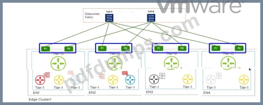
Answer:
Explanation: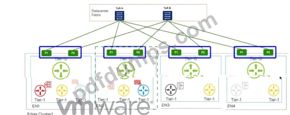
Explanation:
P1 and P2 interfaces on EN2
In aVMware Cloud Foundation (VCF)environment, the interaction between different tiers of logical gateways is governed by the placement ofService Routers (SR). When a Tier-1 Gateway is configured with stateful services, such as aGateway Firewall (GFW), it must operate inActive/Standby (A/S)mode. This ensures that session state is maintained on a single active node at any given time.
According to the provided diagram and VCF architectural guidelines, theActive Tier-1 SRis hosted onEdge Node 2 (EN2). In a multi-tier NSX design, the Tier-1 gateway is logically connected to the Tier-0 gateway via an internal transit segment (often referred to as the Router Link). While the Tier-0 gateway itself is running inActive/Active (A/A)mode across all nodes (EN1 through EN4) to provide high-bandwidth ECMP to the physical Top-of-Rack (ToR) switches, the Tier-1's path to the external world is constrained by its own current location.
Traffic originating from a workload segment attached to this Tier-1 will be processed by the GFW onEN2.
From there, the packet must exit to the physical network via the Tier-0 uplinks. Because the Tier-1 SR is localized to EN2, it will utilize the local Tier-0 instances and their corresponding physical uplinks located on that same node to avoid unnecessary inter-edge "East-West" hair-pinning over the Geneve overlay.
The highlighted optionsP1 and P2 on EN2represent the specific physical/logical uplink paths (VLAN- backed) that the Tier-1 GFW on EN2 will use to reachToR A and ToR B. Even though EN1, EN3, and EN4 also have active Tier-0 paths, the stateful nature of the Tier-1 on EN2 means its North-South traffic flow is anchored to the uplinks of its current host node. Therefore, to identify the ECMP paths actively utilized by that specific stateful Tier-1 service, the administrator must look at the uplink interfaces (P1/P2) associated with the node where that Tier-1 is active.
NEW QUESTION # 16
An administrator is troubleshooting why workloads in NSX cannot reach the external network 10.100.0.0/16.
The Tier-0 Gateway is in Active/Active mode and has the following configuration:
* Uplink-1 (VLAN 100): 192.168.100.0/24 -> router R1 at 192.168.100.1
* Uplink-2 (VLAN 101): 192.168.101.0/24 -> router R2 at 192.168.101.1
* A static route for 10.100.0.0/16 was added with both next-hops (192.168.100.1 and 192.168.101.1).
* The Scope of this route is set to Uplink-1.
Symptoms:
* Virtual Machines (VMs) cannot reach 10.100.0.0/16
* Traceroute from the VM stops at the Tier-0 gateway with "Destination Net Unreachable"
* Pings from the Edge nodes to both 192.168.100.1 and 192.168.101.1 are success What explains why workloads in NSX cannot reach the external network?
- A. The static route Scope is set to only one uplink interface, but the next-hops are on two different VLANs.
- B. The physical routers are missing return routes.
- C. Static routes do not support Equal Cost Multi-Pathing (ECMP) in NSX.
- D. The next-hops should have been configured as the Tier-0's own uplink IPs instead of the routers IPs.
Answer: A
Explanation:
Comprehensive and Detailed 250 to 350 words of Explanation From VMware Cloud Foundation (VCF) documents:
Troubleshooting routing in a VMware Cloud Foundation (VCF) environment requires a deep understanding of how theNSX Tier-0 Gatewayprocesses forwarding entries. In anActive/Activeconfiguration, the Tier-0 gateway is designed to utilize ECMP (Equal Cost Multi-Pathing) to distribute traffic across multiple paths to the physical network.
The specific failure described-where a traceroute fails at the Tier-0 with "Destination Net Unreachable" despite the Edge nodes having basic ping connectivity to the routers-points toward a routing table entry error rather than a physical connectivity issue. In NSX, when a static route is created, an administrator has the option to set a"Scope."The Scope explicitly tells the NSX routing engine which interface should be used to reach the defined next-hops.
In this scenario, the administrator has defined two next-hops (R1 and R2) but has restricted the scope of the static route toUplink-1 only. Because R2 (192.168.101.1) is on a different subnet/VLAN (VLAN 101) that is associated withUplink-2, the Tier-0 gateway cannot resolve the next-hop for R2 via Uplink-1. Furthermore, if the gateway detects an inconsistency between the defined next-hop and the scoped interface, it may invalidate the route or fail to install it correctly in the forwarding information base (FIB) for the service router.
According to VMware documentation, theScopeshould typically be left as "All Uplinks" or carefully matched to the interfaces that have Layer 2 reachability to the next-hop. By scoping it to only Uplink-1, the router R2 becomes unreachable for that specific route entry. Even for R1, if the hashing mechanism of the Active
/Active Tier-0 attempts to use a component of the gateway not associated with that scope, the traffic will fail.
The error "Destination Net Unreachable" at the Tier-0 hop confirms that the Tier-0 has no valid, functional path in its routing table for the 10.100.0.0/16 network due to this scoping conflict.
NEW QUESTION # 17
An administrator is responsible for managing a VMware Cloud Foundation (VCF) Private Cloud consisting of a single VCF Fleet with a single Workload Domain.
The administrator has been tasked with configuring NSX to support the new Virtual Desktop Infrastructure (VDI) solution that allows users to securely access a mainframe- based application located on the physical network. The VDI solution will use a dedicate DHCP solution for each of the the desktop pool segments and static addresses for all VDI management components.
The administrator completes the following steps towards configuring DHCP:
1. Creates a new tier-1 gateway (vdi-tier-1) and links it to the tier-0 gateway (gw-tier-0).
2. Creates one new segment for vdi management (vdi-seg-01) and connects it to vdi-tier-1.
3. Creates two new segments for virtual desktops (vdi-seg-02 and vdi-seg-03) and connects them to vdi-tier-1.
Drag and drop the six steps from the list of Possible Steps on the left and place them in order in to the Solution Steps. (Choose six.)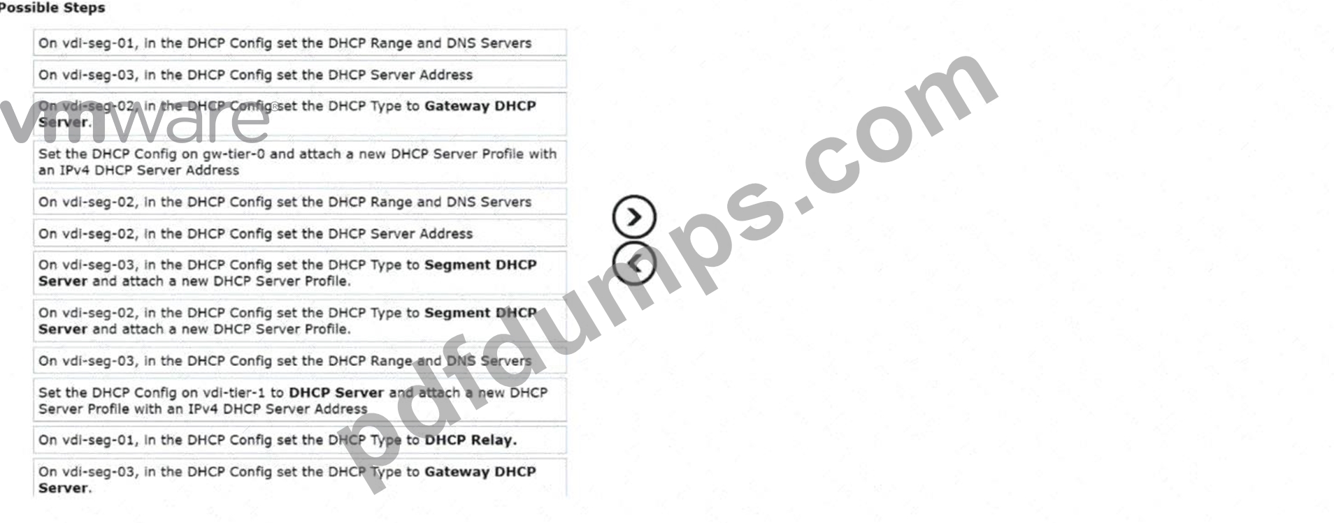
Answer:
Explanation: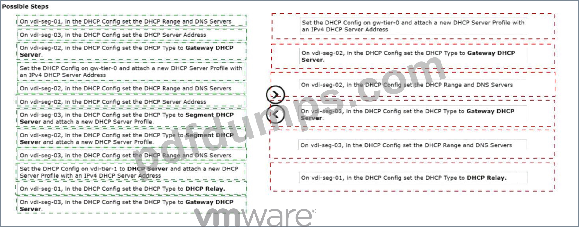
Explanation:
For the VDI solution requiring dedicated DHCP for desktop pool segments and static addresses for management components, the correct sequence of steps to configure DHCP is as follows:
* Set the DHCP Config on vdi-tier-1 to DHCP Server and attach a new DHCP Server Profile with an IPv4 DHCP Server Address.This establishes the Tier-1 gateway as the local DHCP service provider for its attached segments.
* On vdi-seg-02, in the DHCP Config set the DHCP Type to Gateway DHCP Server.This instructs the segment to use the DHCP server service configured on its parent Tier-1 gateway.
* On vdi-seg-02, in the DHCP Config set the DHCP Range and DNS Servers.Defines the specific IP pool and network settings for the first desktop pool.
* On vdi-seg-03, in the DHCP Config set the DHCP Type to Gateway DHCP Server.Instructs the second desktop segment to also leverage the Tier-1 DHCP service.
* On vdi-seg-03, in the DHCP Config set the DHCP Range and DNS Servers.Defines the IP pool for the second desktop pool.
* On vdi-seg-01, in the DHCP Config set the DHCP Type to DHCP Relay.Since management components use static addresses provided by an external mainframe-based solution or dedicated physical infrastructure, a relay is used rather than a local server to ensure proper network isolation and policy enforcement for the physical mainframe application.
NEW QUESTION # 18
An administrator needs to prevent the datacenter from advertising any internal prefixes toward a new VPC, while still ensuring the VPC receives a default route learned from the datacenter's upstream network. Where should the routing policy be applied?
- A. On the provider Tier-0 neighbor.
- B. On the VPC transit gateway.
- C. On each segment default gateway.
- D. On the Tier-1 gateway.
Answer: B
Explanation:
Comprehensive and Detailed 250 to 350 words of Explanation From VMware Cloud Foundation (VCF) documents:
In theVMware Cloud Foundation (VCF) 9.0andNSX VPCarchitecture, theTransit Gateway (TGW)is the central routing element that interconnects VPCs to each other and to the provider's infrastructure (Tier-0 or VRF gateways). It acts as the "Project-level" gateway that aggregates North-South traffic.
To control the visibility of routes within a specific VPC, the administrator must utilizeRoute Filteringat the VPC's boundary. When a VPC is attached to a Transit Gateway, a logical interface is created. To prevent the data center's internal prefixes (such as management networks or other tenant subnets) from being seen by the VPC while still providing a path to the internet, a prefix list or route map should be applied to theVPC Transit Gateway. This policy will explicitly "Deny" specific internal CIDR ranges while "Permitting" the
$0.0.0.0/0$ default route advertisement from the provider.
Applying the policy at theTier-1 gateway(Option B) is technically similar but in the VPC model, the "Tier-1" is often an obscured or automated component of the VPC itself; the Transit Gateway is the designed administrative point for inter-project and North-South policy enforcement. Applying it at theprovider Tier-0 neighbor(Option D) would be too global, affecting all VPCs or projects connected to that Tier-0, rather than the "new VPC" specifically. Therefore, the Transit Gateway provides the necessary granular control for multi- tenant isolation and routing optimization as per the VCF 9.0 networking model.
NEW QUESTION # 19
An administrator implements route leaking between the Tier-0 gateways to enhance east/west communication because the physical L3 devices are oversubscribed.
Where should route-maps be configured based on the architecture observed in the diagram?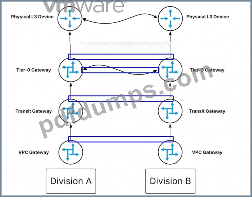
Answer:
Explanation: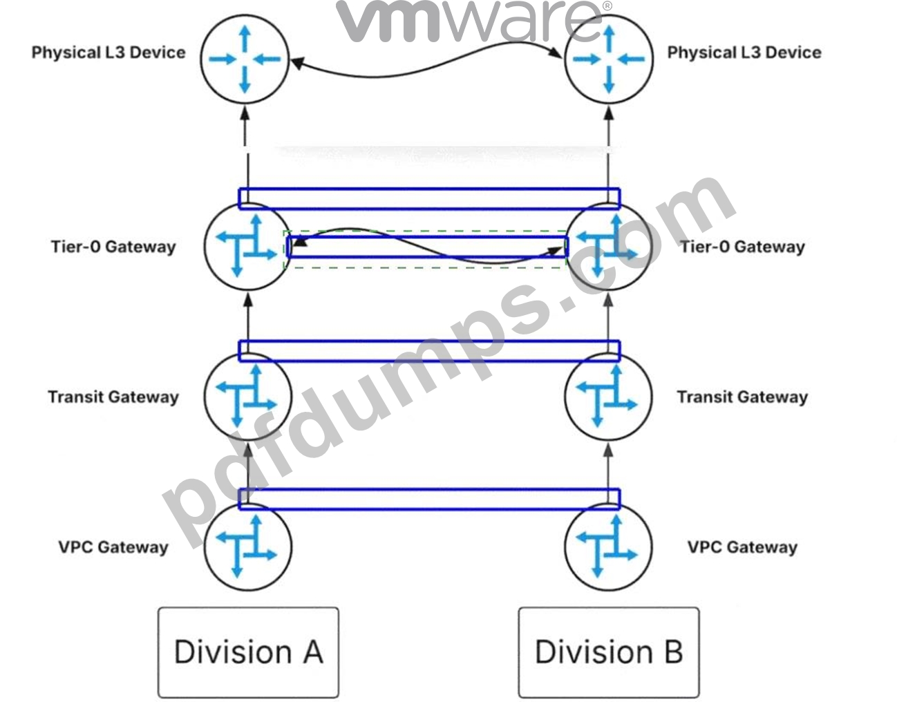
Explanation:
The administrator should click on theblue box representing the logical link between the two Tier-0 Gateways.
In the multi-tenant architecture ofVMware Cloud Foundation (VCF) 9.0, networking is structured hierarchically with VPC Gateways, Transit Gateways, and Tier-0 Gateways. Under normal conditions, traffic between isolated divisions (such as Division A and Division B) that need to communicate might be routed
"North" all the way to thePhysical L3 Devices(the physical core routers) before being routed back down.
However, if these physical devices are oversubscribed or reaching their throughput limits, this creates a performance bottleneck.
To optimize this flow, NSX allows forRoute Leakingat the Tier-0 layer. By establishing a logical peering or connection directly between twoTier-0 Gatewayswithin the virtual fabric, administrators can exchange routing information (prefixes) between the two environments without the traffic ever leaving the SDDC.
To control exactly which networks are shared and to prevent routing loops or unauthorized access,Route- Mapsmust be applied at this inter-gateway connection point. These route-maps define the "Permit" or "Deny" statements for specific IP prefixes being "leaked" from one routing table to another. By clicking the highlighted link between the Tier-0 Gateways, the administrator is targeting the specific control plane interface where these prefix exchanges occur. This configuration ensures that East-West traffic between Division A and Division B is handled locally by theNSX Edge Nodes, effectively bypassing the oversubscribed physical L3 devices and significantly reducing latency and physical network congestion.
NEW QUESTION # 20
When using a DHCP Relay on a segment, which design restriction must be considered?
- A. DHCP Relay service is available to all the other segments in the network.
- B. DHCP settings, DHCP options, and static bindings cannot be configured on the segment.
- C. DHCP settings, DHCP options, and static bindings can be configured on the segment.
- D. DHCP client requests cannot be relayed to the external DHCP servers.
Answer: B
Explanation:
Comprehensive and Detailed 250 to 350 words of Explanation From VMware Cloud Foundation (VCF) documents:
InVMware Cloud Foundation (VCF)networking, IP address management within an NSX segment can be handled by either the native NSX DHCP server or by an external DHCP server. When an administrator chooses to use an existing external corporate DHCP infrastructure, they must configure aDHCP Relayon the logical segment.
The DHCP Relay works by intercepting the initial DHCP Discover broadcast from a workload VM and forwarding it (as a unicast packet) to the specified IP address of the external DHCP server. However, NSX enforces a strict mutual exclusivity in its configuration logic to prevent conflicts and unpredictable address assignments.
According to the "NSX-T Data Center Administration Guide," once a segment is configured to use aDHCP Relay profile, the native NSX DHCP capabilities for that specific segment are disabled. This means that DHCP settings, DHCP options, and static bindings cannot be configured on that segment(Option A). All such configurations, including IP reservations and scope options (like DNS or NTP), must be managed centrally on the external DHCP server.
Option C is incorrect because the UI will physically grey out or prevent the entry of native DHCP parameters once the Relay is selected. Option B is incorrect as the primary purpose of a Relay is precisely to forward requests to external servers. Option D is incorrect because a DHCP Relay is configured on a per-segment or per-gateway basis; it is not a "global" service that automatically covers all other segments in the network.
Therefore, the architectural trade-off when choosing a Relay is the shift of all management and binding logic to the external physical or virtual DHCP appliance.
NEW QUESTION # 21
An administrator is responsible for the management of a VMware Cloud Foundation (VCF) Fleet that consists of two VCF instances that are located in different physical locations. The administrator has been tasked with configuring a VPN between the two locations and has been tasked with identifying the two supported NSX Gateway configurations for an IPSec VPN. Drag and drop two items from the list of Possible Configurations into the list of Supported Configurations in any order.(Choose two.)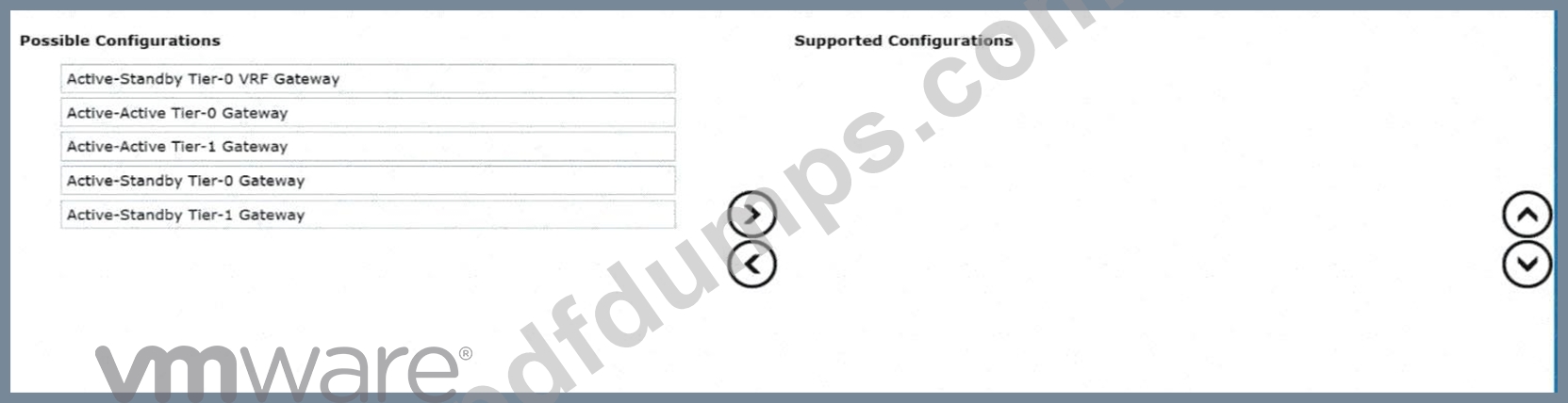
Answer:
Explanation: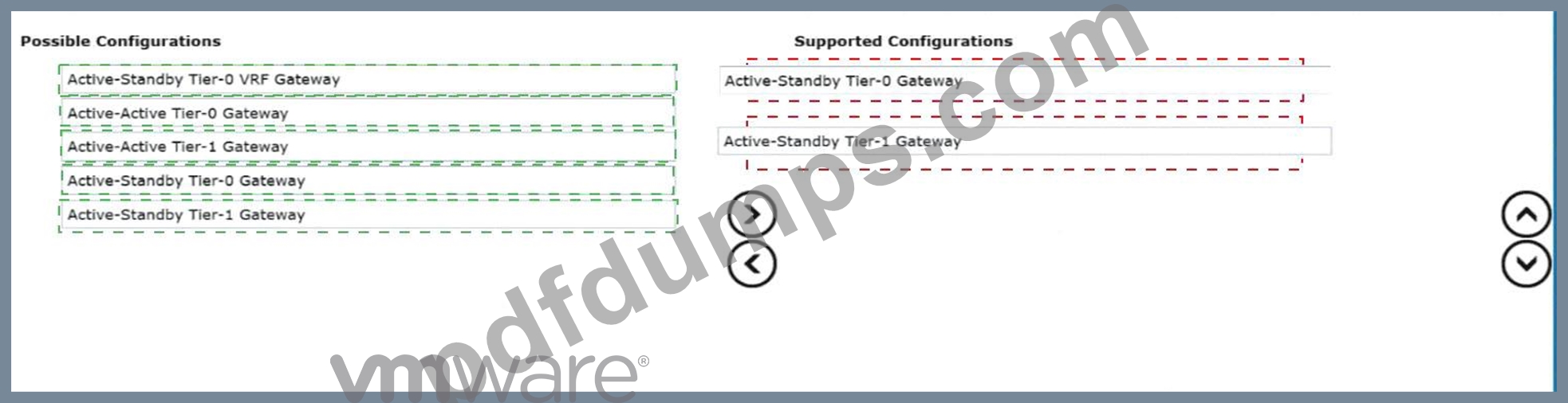
Explanation:
* Active-Standby Tier-0 Gateway
* Active-Standby Tier-1 Gateway
In aVMware Cloud Foundation (VCF)multi-site or multi-instance architecture, established viaNSX Federation, secure connectivity between sites is often achieved throughIPSec VPN. IPSec VPN is considered a stateful service within the NSX networking stack.
Stateful services-which also include NAT and Load Balancing-require a centralized point of processing to maintain the security association (SA) and session state tables. In the NSX gateway architecture, this necessitates the presence of aService Router (SR)component. For stateful consistency and to avoid session disruption that would occur if asymmetric traffic were processed by different nodes, these gateways must operate in anActive-Standbyhigh-availability mode.
According to the "NSX-T Data Center VPN Configuration Guide," IPSec VPN services can be deployed on either the provider tier (Tier-0 Gateway) or the tenant tier (Tier-1 Gateway). When configured on a Tier-0 gateway, the VPN typically provides broad connectivity between the physical infrastructure of two sites.
When configured on a Tier-1 gateway, it often provides targeted connectivity for a specific project or department's workload segments.
Configurations involvingActive-Activegateways (whether Tier-0 or Tier-1) do not support the native NSX IPSec VPN service because the ECMP (Equal Cost Multi-Pathing) nature of Active-Active mode could lead to packets belonging to the same VPN tunnel being processed by different Edge nodes, which cannot share the real-time encryption state. Therefore, for an administrator to successfully implement a cross-location VPN in a VCF Fleet, they must ensure the target gateway-be it Tier-0 or Tier-1-is deployed inActive-Standby mode.
NEW QUESTION # 22
An administrator created a new Tier-1 Gateway and is attempting to change the connected gateway for a deployed segment to use the new gateway. In the UI, when the administrator clicks the Connected Gateway dropdown, the new Tier-1 gateway is not shown as an available gateway. What would prevent the new Tier-1 gateway from showing in the list of available gateways?
- A. The Tier-1 Gateway and NSX Segment are in different transport zones.
- B. The Tier-1 Gateway and NSX Segment are connected to different Tier-0 Gateways.
- C. The Tier-1 Gateway connectivity policy is set to "None".
- D. The Tier-1 Gateway is not connected to an NSX Edge Cluster.
Answer: A
Explanation:
Comprehensive and Detailed 250 to 350 words of Explanation From VMware Cloud Foundation (VCF) documents:
InVMware Cloud Foundationnetworking, the relationship between segments and gateways is governed by the underlyingTransport Zone (TZ)configuration. A Transport Zone defines the potential span of a virtual network-specifically, which hosts and edges can participate in that network.
When an administrator creates anNSX Segment, they must associate it with a specific Transport Zone (either Overlay or VLAN). Similarly, when aTier-1 Gatewayis created, its reach is determined by the Transport Zones available on the Transport Nodes (Edges and ESXi hosts) where it is instantiated. For a Segment to be attached to a Tier-1 Gateway, both objectsmust reside within the same Transport Zone.
If the Segment was created in "Overlay-TZ-01" but the new Tier-1 Gateway is only associated with "Overlay- TZ-02" (or if one is in a VLAN TZ and the other in an Overlay TZ), the NSX Manager UI will filter out the incompatible gateway to prevent an invalid configuration. The logical switch (Segment) cannot bind to a gateway if they do not share a common broadcast or encapsulation domain defined by the Transport Zone.
Option A is incorrect because a Tier-1 Gateway does not strictlyrequirean Edge Cluster unless it is providing stateful services (like NAT, LB, or Firewall). It can exist purely as a distributed component on the hypervisors. Option B (Connectivity Policy) determines if the T1 advertises routes to the T0, but it doesn't prevent a segment from connecting to it. Option D is also incorrect, as a Tier-1 Gateway can be moved between Tier-0s, or even exist without a Tier-0 connection initially. Therefore, theTransport Zone mismatch is the fundamental architectural barrier preventing the gateway from appearing in the selection list.
NEW QUESTION # 23
An administrator is investigating packet loss reported by workloads connected to VLAN segments in an NSX environment. Initial checks confirm:
* All VMs are powered on
* VLAN segment IDs are consistent across transport nodes
* Physical switch configurations are correct.
Which two NSX tools can be used to troubleshoot packet loss on VLAN Segments? (Choose two.)
- A. Packet Capture
- B. Traceflow
- C. Flow Monitoring
- D. Activity Monitoring
- E. Live Flow
Answer: A,B
Explanation:
Comprehensive and Detailed 250 to 350 words of Explanation From VMware Cloud Foundation (VCF) documents:
In a VMware Cloud Foundation (VCF) environment, troubleshooting packet loss requires tools that can provide visibility into both the logical and physical paths of a packet. When dealing specifically withVLAN segments(as opposed to Overlay segments), the traffic does not leave the host encapsulated in Geneve; instead, it is tagged with a standard 802.1Q header.
Traceflowis the primary diagnostic tool within NSX for identifying where a packet is being dropped. It allows an administrator to inject a synthetic packet into the data plane from a source (such as a VM vNIC) to a destination. The tool then reports back every "observation point" along the path, including switching, routing, and firewalling. If a packet is dropped by a Distributed Firewall (DFW) rule or a physical misconfiguration that wasn't caught initially, Traceflow will explicitly state at which stage the packet was lost.
Packet Captureis the second essential tool. NSX provides a robust, distributed packet capture utility that can be executed from the NSX Manager CLI or UI. This tool allows administrators to capture traffic at various points, such as the vNIC, the switch port, or the physical uplink (vmnic) of the ESXi Transport Node. By comparing captures from different points, an administrator can determine if a packet is reaching the virtual switch but failing to exit the physical NIC, or if return traffic is reaching the host but not the VM.
Options likeFlow MonitoringandLive Floware excellent for observing traffic patterns and session statistics (IPFIX), but they are less effective for pinpointing the exact cause of "packet loss" compared to the granular, packet-level analysis provided by Traceflow and Packet Capture.Activity Monitoringis typically used for endpoint introspection and user-level activity, which is irrelevant to Layer 2/3 packet loss troubleshooting.
NEW QUESTION # 24
An administrator has a VMware Cloud Foundation (VCF) instance. A critical NSX security update has been released by Broadcom. How can the administrator install the NSX update?
- A. Download the NSX patch to VCF Operations. Apply it using VCF Operations Fleet Management.
- B. Download the NSX patch to the NSX Manager. Apply it using VCF Operations Fleet Management.
- C. Download the NSX patch to VCF Operations. Apply it using NSX Manager.
- D. Download the NSX patch to the NSX Manager. Apply it using NSX Manager.
Answer: A
Explanation:
Comprehensive and Detailed 250 to 350 words of Explanation From VMware Cloud Foundation (VCF) documents:
In the unified architecture ofVMware Cloud Foundation (VCF) 9.0, the management paradigm has shifted towards a more centralized "Fleet Management" approach. Historically, in VCF 4.x and 5.x, updates were primarily managed via the SDDC Manager using the Lifecycle Management (LCM) engine. However, with the integration advancements in version 9.0,VCF Operations(formerly part of the Aria/vRealize suite) has taken on a more direct role in the orchestration of updates across the entire VCF "Fleet." To comply with the VCF operational model, administrators no longer apply patches directly within the component managers (like NSX Manager or vCenter) if they wish to remain within the supported, automated framework. Instead, the workflow begins by downloading the bundle or patch toVCF Operations. This ensures that the update is validated against the currentBill of Materials (BOM)and that all dependencies- such as compatibility with the underlying ESXi versions or the management vCenter-are checked before any changes are committed.
Once the patch is available in VCF Operations, the administrator utilizesFleet Managementto apply it. This service orchestrates the update across all NSX Managers and Transport Nodes (Edges and Hosts) in a controlled, non-disruptive manner. If the administrator were to apply the patch directly in NSX Manager (Option D), the SDDC Manager and VCF Operations databases would go out of sync, leading to a
"configuration drift" where the system no longer knows which version is actually running, potentially breaking future automated lifecycle tasks. Therefore, the centralized download and application throughVCF Operations Fleet Managementis the verified procedure for maintaining a healthy and compliant VCF 9.0 environment.
NEW QUESTION # 25
An administrator has noticed an issue in a freshly deployed VMware Cloud Foundation (VCF) environment where the BGP neighborship between the Tier-0 gateway and a physical router remains in the Idle state. Pings between the uplink IPs are successful. What is the issue?
- A. Overlay MTU too low.
- B. Autonomous System number mismatch.
- C. Distributed Firewall blocking traffic.
- D. Geneve tunnel down.
Answer: B
Explanation:
Comprehensive and Detailed 250 to 350 words of Explanation From VMware Cloud Foundation (VCF) documents:
In the context ofVMware Cloud Foundation (VCF), particularly versions 5.x and the architectural advancements inVCF 9.0, the establishment of North-South routing via theNSX Tier-0 Gatewayis a critical post-deployment or bring-up task. The Tier-0 gateway usesBorder Gateway Protocol (BGP)to peer with physical Top-of-Rack (ToR) switches to exchange reachability information for the overlay networks.
When a BGP session is reported in the"Idle"state, it indicates that the BGP Finite State Machine (FSM) is at its first stage and is not yet attempting a TCP connection, or it has encountered an error that forced it back to this state. According to VMware VCF documentation and NSX troubleshooting guides, if the administrator can successfully ping between the Tier-0 uplink IP and the physical router interface,Layer 3 reachability is confirmed. This eliminates issues related to physical cabling, VLAN tagging on the trunk ports, or basic IP interface configuration.
The primary reason a BGP session remainsIdledespite successful ICMP reachability is a configuration mismatch. Specifically, anAutonomous System (AS) number mismatchis the most frequent culprit. BGP requires that the "Remote AS" configured on the Tier-0 gateway matches the "Local AS" of the physical peer.
If the SDDC Manager automated workflow or the manual configuration in NSX Manager contains a typo in these values, the protocol handshake will fail immediately.
While aDistributed Firewall (DFW)could technically block port 179, it is not common in a "freshly deployed" environment for the default rules to block the Edge Node's control plane traffic.Geneve tunnelsand MTU issues(Option C and D) typically affect the data plane-causing packet loss for encapsulated guest VM traffic-but they do not prevent the BGP control plane (running over standard TCP) from moving beyond the Idle state. Therefore, verifying the AS numbers in the VCF Planning and Preparation Workbook against the physical switch configuration is the verified resolution path.
NEW QUESTION # 26
Which two statements describe the recommended strategy for configuring and synchronizing security policies across Federated NSX sites? (Choose two.)
- A. Security policies should be defined locally on each LM and only synchronized manually by an administrator to prevent accidental conflicts.
- B. Consistency is achieved by ensuring all security groups have the exact same name on every Federated site's Local Manager (LM).
- C. The Global Manager only synchronizes networking (L2/L3) configurations. Security rules must be configured separately on each site.
- D. Local Managers (LMs) can define local policies, but any global policies defined on the GM always take precedence over the local ones.
- E. Security policies, such as Distributed Firewall rules and security groups, must be defined as global policies on the Global Manager (GM).
Answer: D,E
Explanation:
Comprehensive and Detailed 250 to 350 words of Explanation From VMware Cloud Foundation (VCF) documents:
NSX Federationis the cornerstone of multi-siteVMware Cloud Foundation (VCF)security, enabling administrators to maintain a consistent security posture across geographically dispersed data centers. The management of security in a Federated environment relies on a hierarchical relationship between theGlobal Manager (GM)andLocal Managers (LMs).
According to VMware documentation, the recommended strategy is to defineGlobal Security Policieson the Global Manager (Option B). When a security group or a Distributed Firewall (DFW) rule is created on the GM, it is automatically synchronized to all registered Local Managers. This ensures that a "Finance App" security policy is identical in AZ1 and AZ2. These global objects are identified by a specific tag in the local NSX Manager UI, indicating they are managed globally and cannot be modified locally.
Furthermore, NSX handles the coexistence of global and local rules through a specific evaluation order (Option D). In the NSX DFW category structure,Global Categories(managed by the GM) are evaluated beforeLocal Categories(managed by the LM). This ensures that corporate-wide security mandates (like
"Block All SSH to Management") defined at the GM level are enforced first and cannot be bypassed by localized site-level rules.
Option A is incorrect because manual naming consistency is prone to error and does not provide actual synchronization. Option C and E are incorrect as they contradict the fundamental purpose of Federation, which is to centralize management and automate synchronization to prevent configuration drift and security gaps. Therefore, defining policies on the GM and utilizing the inherent precedence of global rules is the verified design best practice for VCF Federation.
NEW QUESTION # 27
An administrator has observed an NSX Local Manager (LM) outage at the secondary Site. However, the NSX Global Manager (GM) in secondary Site remains operational. What happens to data plane operations and policy enforcement at the secondary site?
- A. The data plane operates normally until LM recovery and reconnection.
- B. Only local policies work; global policies cease to apply on the secondary site.
- C. Secondary site must failover all workloads to Primary site.
- D. All traffic is blocked until secondary site LM recovers.
Answer: A
Explanation:
Comprehensive and Detailed 250 to 350 words of Explanation From VMware Cloud Foundation (VCF) documents:
The architecture ofNSX Federationwithin a VCF Multi-Site design is built upon a separation of theControl Planeand theData Plane. This "decoupled" architecture ensures high availability and resiliency even when management components become unavailable.
In NSX Federation, theGlobal Manager (GM)handles the configuration of objects that span multiple locations, while theLocal Manager (LM)is responsible for pushing those configurations down to the local Transport Nodes (ESXi hosts and Edges) within its specific site. When a configuration is pushed, the Local Manager communicates with theCentral Control Plane (CCP)and subsequently theLocal Control Plane (LCP)on the hosts.
If an NSX Local Manager goes offline, the "Management Plane" for that site is lost. This means no new segments, routers, or firewall rules can be created or modified at that site. However, the existing configuration is already programmed into theData Plane(the kernels of the ESXi hosts and the DPDK process of the Edge nodes).
According to VMware's "NSX Multi-Location Design Guide," the data plane remains fully operational during a Management Plane outage. Existing VMs will continue to communicate, BGP sessions on the Edges will remain established, and Distributed Firewall (DFW) rules will continue to be enforced based on the last known good configuration state cached on the hosts. The data plane does not require constant heartbeats from the Local Manager to forward traffic. Therefore, operations continue normally "headless" until the LM is restored and can resume synchronization with the Global Manager and local hosts. Failover to a primary site (Option D) is only necessary if the actual data plane (hosts/storage) fails, not just the management components.
NEW QUESTION # 28
An administrator has a standalone vSphere 8.0 Update 1a deployment that is running with VMware NSX
4.1.0.2 and has to converge the deployment into a new VMware Cloud Foundation (VCF) instance. How can the administrator accomplish this task?
- A. Manually upgrade vSphere to version 9 and uninstall NSX 4. Then use the VCF Installer to converge the vSphere 9.0 environment into a new VCF management domain at which time NSX 9 will be reinstalled.
- B. Use the VCF Installer to converge the existing vSphere 8 and NSX 4 environment into a new VCF management domain. Then use the VCF lifecycle management tools to upgrade to 9.
- C. Manually upgrade both vSphere and NSX to version 9 prior to converging. Then use the VCF Installer to converge the vSphere 9 and NSX 9 instances into a new VCF management domain.
- D. Manually upgrade vSphere to version 9. Then use the VCF Installer to converge the vSphere 9 environment into a new VCF management domain. Then use the VCF lifecycle management tools to upgrade NSX to version 9.
Answer: B
Explanation:
Comprehensive and Detailed 250 to 350 words of Explanation From VMware Cloud Foundation (VCF) documents:
The process of bringing existing infrastructure under VCF management is known as"VCF Import"or
"Convergence."This is a common path for organizations transitioning from siloed management to the full SDDC stack provided by Cloud Foundation.
According to the VCF 5.x and 9.0 documentation, theVCF Installer(specifically the Cloud Foundation Builder and the Import Tool) is designed to ingest existing environments. The verified best practice is to converge the environment at its current, supported version, provided it meets the minimum baseline requirements for the VCF version you are deploying.
In this scenario, vSphere 8.0 U1 and NSX 4.1 are compatible versions that can be imported into a VCF management framework. By using theVCF Installerto converge the existing environment first (Option C), the SDDC Manager takes ownership of the existing vCenter and NSX Manager. Once the environment is
"VCF-aware," the administrator gains the benefit ofSDDC Manager's Lifecycle Management (LCM).
The SDDC Manager then handles the orchestrated, multi-step upgrade to version 9.0. This ensures that the automated "Bill of Materials" (BOM) is strictly followed, ensuring compatibility between vCenter, ESXi, and NSX components. Attempting to manually upgrade components to version 9beforeconvergence (Options A and B) or uninstalling NSX (Option D) creates a "Frankenstein" environment that may not align with the VCF BOM, making the automated convergence process fail or resulting in an unsupported configuration. The principle of VCF is tobring the environment in first, then let VCF manage the upgrades.
NEW QUESTION # 29
An administrator is tasked to configure NSX Federation between separate VMware Cloud Foundation (VCF) Fleets. Which requirement must all sites meet before being added to a Global Manager (GM) for NSX Federation?
- A. All Sites must use the same VTEP VLAN and IP pools.
- B. All sites must have the same NSX version and build.
- C. All sites must be managed by the same VCF instance.
- D. All sites must use identical Tier-0 gateway BGP autonomous system numbers.
Answer: B
Explanation:
Comprehensive and Detailed 250 to 350 words of Explanation From VMware Cloud Foundation (VCF) documents:
NSX Federation, a core component of large-scale VCF deployments across multiple sites or "fleets," introduces a hierarchical management model where aGlobal Manager (GM)orchestrates security policies and networking objects across multipleLocal Managers (LMs).
To ensure stability and compatibility in the communication between the Global Manager and the Local Managers, VMware documentation specifies strictversion parityrequirements. When onboarding a site into a Federation, the Local Manager at that site must be running thesame NSX version and buildas the other sites in the Federation and must be compatible with the Global Manager's version. Discrepancies in versions can lead to synchronization failures, as the API schemas and internal database structures for Global Objects (like Global Segments or Groups) may differ between builds.
While Federation allows for geographic and administrative separation, the underlying software-defined networking stack must be synchronized. Option A is incorrect; in fact, VTEP/TEP VLANs and IP poolsshould be unique to each site to avoid IP conflicts in the transport network, though they must have Layer 3 reachability to one another. Option B is incorrect; unique BGP AS numbers are often preferred for multi-site routing to prevent loops. Option C is also incorrect, as Federation is specifically designed to link different VCF instances (sites) together into a single manageable entity.
In aVCF 5.x or 9.0context, the SDDC Manager helps maintain this requirement by ensuring that the "Bill of Materials" (BOM) is consistent across sites intended for Federation. Before the GM can successfully register and "push" configuration to an LM, the handshake process validates the build version to prevent the corruption of the global intended state.
NEW QUESTION # 30
In an NSX environment, an administrator is observing low throughput and intermittent congestion between the Tier-0 Gateway and the upstream physical routers. The environment was designed for high availability and load balancing, using two Edge Nodes deployed in Active/Active mode. The administrator enables ECMP on the Tier-0 gateway, but the issues persist. Which action would address low throughput and congestion?
- A. Deploy additional Edge nodes.
- B. Add an additional vNIC to the NSX Edge node.
- C. Disable NAT on the Tier-0 gateway.
- D. Convert Tier-1 gateways to be edgeless.
Answer: A
Explanation:
Comprehensive and Detailed 250 to 350 words of Explanation From VMware Cloud Foundation (VCF) documents:
When aVMware Cloud Foundation (VCF)environment experiences North-South congestion at theTier-0 Gateway, it typically indicates that the processing capacity of the existingNSX Edge Nodeshas been reached.
In anActive/Activeconfiguration, the Tier-0 gateway utilizesEqual Cost Multi-Pathing (ECMP)to distribute traffic across all available Edge nodes in the cluster.
If a two-node Edge cluster is saturated despite ECMP being enabled, the standard "Scale-Out" procedure is to deploy additional Edge nodes(Option D). NSX supports up to8 Edge nodesin a single cluster for a Tier-0 gateway. By adding more nodes, the administrator increases the total number of CPU cores dedicated to the DPDK (Data Plane Development Kit) packet processing engine. Each additional node provides more
"bandwidth lanes" for the ECMP hash to utilize, effectively multiplying the aggregate throughput capability of the North-South exit point.
Option A is incorrect because "edgeless" Tier-1 gateways (Distributed Routers only) improve East-West performance by keeping traffic on the ESXi hosts, but they do not help with North-South traffic that must eventually hit a Tier-0 Service Router on an Edge. Option B (Disabling NAT) might reduce CPU overhead slightly, but it doesn't solve a fundamental capacity bottleneck and is often not an option due to architectural requirements. Option C (Adding a vNIC) does not increase the underlying compute/DPDK processing power of the Edge VM and can sometimes complicate the load-balancing hash.
In VCF operations, this expansion is handled via theSDDC Manager, which can automate the addition of new Edge nodes to an existing cluster, ensuring they are configured symmetrically with the correct uplink profiles and BGP peering sessions. This horizontal scaling is the verified method for resolving congestion in high-demand VCF networking environments.
NEW QUESTION # 31
The administrator is implementing a multi-location VMware Cloud Foundation (VCF) environment. The design requires centralized security and networking policies across multiple VCF instances. What action must the administrator take to satisfy the requirements?
- A. Deploy a Local Manager (LM) cluster using VCF Operations.
- B. Deploy a Global Manager cluster manually.
- C. Use SDDC Manager to deploy a Global Manager cluster.
- D. Use VCF Installer to deploy a Local Manager (LM) cluster.
Answer: C
Explanation:
Comprehensive and Detailed 250 to 350 words of Explanation From VMware Cloud Foundation (VCF) documents:
In aVMware Cloud Foundation (VCF)Multi-Site or Multi-Instance design, the requirement for "centralized security and networking policies" is fulfilled byNSX Federation. Federation introduces theGlobal Manager (GM), which provides a single pane of glass to manage objects that span across different VCF sites.
Historically, in early versions of NSX-T, Global Managers were deployed manually. However, within the VCF framework (VCF 4.x, 5.x, and 9.0), the deployment and lifecycle management of theGlobal Manager clusterare fully integrated intoSDDC Manager. According to the VCF Design Guide and "Deploying and Configuring NSX Federation" documents, the verified best practice is to use the SDDC Manager UI or API to trigger the GM deployment.
When an administrator usesSDDC Manager(Option C), the process is automated: SDDC Manager deploys the appliances, configures the virtual IP (VIP), handles the certificate management, and ensures that the GM is properly integrated into the VCF Bill of Materials (BOM). This automation is critical for maintaining supportability, as it ensures the GM version is perfectly aligned with the Local Managers (LMs) already present in the Management and Workload domains.
Option A is discouraged because manual deployments lead to configuration drift and issues with future automated upgrades. Option B is incorrect as VCF Operations is for monitoring, not deployment. Option D is incorrect because theVCF Installeris primarily used for the initial "bring-up" of the Management Domain; subsequent management components like GMs are handled by the SDDC Manager once the initial site is active. Thus, SDDC Manager is the authoritative tool for deploying the Global Manager cluster in a VCF multi-location environment.
NEW QUESTION # 32
An administrator changed the SFTP server used for scheduled NSX Manager backups. The backup jobs now fail with the error "Host KEY Verification Failed." The connectivity and credentials are correct. How would an administrator resolve the error?
- A. Trust the certificate on the SFTP server.
- B. Turn Off Backup encryption.
- C. Use the NSX cluster VIP as the SFTP endpoint.
- D. Update the SSH fingerprint.
Answer: D
Explanation:
Comprehensive and Detailed 250 to 350 words of Explanation From VMware Cloud Foundation (VCF) documents:
InVMware Cloud Foundation (VCF), theNSX Manageruses the SFTP protocol to securely transfer configuration backups to an external repository. SFTP is built on top of the SSH protocol, which relies on a
"Trust on First Use" (TOFU) model for verifying the identity of the remote host.
When an NSX Manager first connects to an SFTP server, it retrieves the server'sSSH Public Key Fingerprint and stores it in its local known_hosts equivalent database. This fingerprint ensures that future connections are made to the same, verified server, preventing man-in-the-middle attacks.
The error"Host KEY Verification Failed"occurs when the administrator changes the SFTP server (or if the SFTP server's OS was reinstalled/keys regenerated). Even if the IP address remains the same, the new server presents a different SSH fingerprint than the one currently cached in the NSX Manager configuration.
Because the signatures do not match, the NSX Manager aborts the connection for security reasons.
To resolve this issue, the administrator mustUpdate the SSH fingerprint(Option B) within the NSX Manager backup settings. This involves:
* Retrieving the new fingerprint from the SFTP server (e.g., via ssh-keyscan).
* Navigating to System > Lifecycle > Backup & Restore in the NSX Manager.
* Editing the File Server configuration and pasting the new fingerprint into the appropriate field.
Option A is incorrect as it does not address the SSH protocol handshake failure. Option C is incorrect because SFTP/SSH uses fingerprints, not SSL/TLS certificates. Option D is irrelevant as it changes the source
/destination of the connection but does not fix the underlying trust mismatch. Therefore, updating the fingerprint is the verified operational step to restore the automated backup workflow in VCF.
NEW QUESTION # 33
Which of the following statements is true when configuring Remote Tunnel End Points (RTEPs) with NSX Federation?
- A. TEP and RTEP networks must use separate physical NICs.
- B. DHCP must be used to assign IP addresses to the RTEP.
- C. RTEP needs to be configured on only one edge node.
- D. The default MTU for the RTEP network is 1500.
Answer: D
Explanation:
Comprehensive and Detailed 250 to 350 words of Explanation From VMware Cloud Foundation (VCF) documents:
In anNSX Federationdeployment, which is a key component of multi-siteVMware Cloud Foundation (VCF)architectures, theRemote Tunnel End Point (RTEP)is used specifically for inter-site communication.
While standard TEPs (Tunnel End Points) handle overlay traffic within a single site (East-West), RTEPs facilitate the encapsulation of traffic that needs to traverse the Layer 3 network between different geographical locations.
A critical design consideration for RTEP is theMaximum Transmission Unit (MTU). Within a local VCF site, jumbo frames (MTU 1600 or 9000) are highly recommended and often required for the Geneve overlay to account for encapsulation overhead. However, when traffic leaves a site to travel over a WAN or a provider's long-haul network, it often encounters physical infrastructure that only supports the standard internet MTU of1500 bytes.
According to VMware's "NSX Federation Design Guide," the default MTU setting for the RTEP configuration is1500. This ensures that inter-site traffic can pass through standard routers and VPNs without being dropped due to size constraints. If the inter-site physical links support larger frames, this value can be increased, but 1500 remains the baseline compatible default.
Regarding the other options:Ais incorrect because TEP and RTEP can share the same physical N-VDS and physical NICs (pNICs) by using different VLANs or subnets.Bis incorrect because every Edge node within a cluster that is participating in the Federation must have an RTEP configured to ensure high availability and proper traffic processing for global segments.Dis incorrect as IP addresses for RTEPs are typically assigned viaStatic IP Poolsmanaged within NSX to ensure consistency and ease of tracking across sites, rather than relying on DHCP which is less common in data center backbone configurations.
NEW QUESTION # 34
A sovereign cloud provider has a VMware Cloud Foundation (VCF) stretched Workload Domain across two data centers (AZ1 and AZ2), where site connectivity via Layer 3 is provided by the underlay. The following NSX details are included in the design:
* Each site must host its own local NSX Edge Cluster for availability zones.
* Tier-0 gateways must be configured in active/active mode with BGP ECMP to local top-of-rack switches.
* Inter-site Edge TEP traffic must not cross the inter-DC link.
* SDDC Manager is used to automate NSX deployment.
During deployment of the Edge Cluster for AZ2, the SDDC Manager workflow fails because the Edge transport nodes' TEP IPs are not reachable from the ESXi transport nodes. Which step ensures correct Edge Cluster deployment in multi-site stretched domains?
- A. Create an AZ2-specific Edge TEP IP pool and map it to the AZ2 uplink profile before deploying the Edge Cluster.
- B. Disable the liveness check during Edge deployment in SDDC Manager.
- C. Reuse the TEP IP pool from AZ1.
- D. Configure BGP neighbors before deploying the Edge Cluster.
Answer: A
Explanation:
Comprehensive and Detailed 250 to 350 words of Explanation From VMware Cloud Foundation (VCF) documents:
In aVMware Cloud Foundation (VCF)stretched cluster or Multi-Availability Zone (Multi-AZ) architecture, the networking design must account for the fact that AZ1 and AZ2 typically reside in different Layer 3 subnets. While the NSX Overlay provides Layer 2 adjacency for virtual machines across sites, the underlying Tunnel Endpoints (TEPs)must be able to communicate over the physical Layer 3 network.
According to the VCF Design Guide for Multi-AZ deployments, when stretching a workload domain, each availability zone should have its own dedicatedTEP IP Pool. This is because TEP traffic is encapsulated (Geneve) and routed via the physical underlay. If the Edge nodes in AZ2 were to use the same IP pool as AZ1 (Option C), the physical routers would likely encounter routing conflicts or reachability issues, as the subnet for AZ1 would not be natively routable or "local" to the AZ2 Top-of-Rack (ToR) switches.
The failure during the SDDC Manager workflow occurs because the automated "Liveness Check" or "Pre- validation" step attempts to verify that the newly assigned TEP IPs in AZ2 can reach the existing TEPs in the environment. To resolve this and ensure a successful deployment, the administrator must define a uniqueAZ2- specific IP Poolin NSX. Furthermore, this pool must be associated with anUplink Profile(or a Sub-Transport Node Profile in VCF 5.x/9.0) that uses the specific VLAN tagged for TEP traffic in the second data center.
This ensures that the Edge Nodes in AZ2 are assigned IPs that are valid and routable within the AZ2 underlay, allowing Geneve tunnels to establish correctly to the ESXi hosts in both sites without requiring a stretched Layer 2 physical network for the TEP infrastructure.
NEW QUESTION # 35
During a design review, the administrator is asked to explain which underlying technology enables the NSX Edge to perform fast packet processing and achieve near line-rate performance for Virtual Network Functions (VNFs). Which technology is leveraged in the NSX Edge for fast packet processing?
- A. Data Plane Development Kit (DPDK)
- B. AMD Power Now
- C. Non-Uniform Memory Access (NUMA)
- D. Intel Speed Step
Answer: A
Explanation:
Comprehensive and Detailed 250 to 350 words of Explanation From VMware Cloud Foundation (VCF) documents:
TheNSX Edgeis the workhorse of the VMware Cloud Foundation networking stack, handling demanding tasks like Geneve encapsulation, NAT, Firewalling, and BGP routing. To achieve the throughput required for modern data centers-often exceeding 10Gbps or even 40Gbps per node-NSX leverages theData Plane Development Kit (DPDK).
Traditional packet processing in a standard Linux or Unix kernel is often a bottleneck. The kernel must handle interrupts, context switching between user space and kernel space, and complex buffer management for every packet. This "overhead" limits the speed at which a CPU can move packets.DPDKchanges this by bypassing the standard kernel networking stack entirely. It operates inUser Spaceand uses a "polling" mechanism rather than an "interrupt-driven" one.
In an NSX Edge VM or Bare Metal node, specific CPU cores are dedicated to the DPDK process (often called theDatapathorFP-Main). these cores "spin" at 100% utilization, constantly checking the NICs for new packets. Because there is no context switching and the process has direct access to the network hardware buffers, the Edge can process millions of packets per second (Mpps) with extremely low latency.
WhileNUMA(Option C) is a hardware architecture that NSX is "aware" of to optimize memory access, and Intel Speed Step/AMD Power Now (Options B and D) are power management features,DPDKis the actual software technology that enables the "fast packet processing" capability of the VCF networking solution. This is why VMware documentation emphasizes the importance of ensuring that Edge VMs are sized correctly with enough "High-Performance" cores to support the intended DPDK throughput.
NEW QUESTION # 36
......
VMware 3V0-25.25 Exam Syllabus Topics:
| Topic | Details |
|---|---|
| Topic 1 |
|
| Topic 2 |
|
| Topic 3 |
|
| Topic 4 |
|
| Topic 5 |
|
Reliable Professional Level Exams 3V0-25.25 Dumps PDF Jun 28, 2026 Recently Updated Questions: https://studyguide.pdfdumps.com/3V0-25.25-valid-exam.html